Rescuing Firmware
Rescuing hardware that fails to boot after firmware flashing
Recovering corrupted firmware with a programmer
Before you begin
If you are reading this page, your hardware likely failed to boot due to improper firmware flashing or update. This guide will help you re‑flash the firmware using a programmer.
Before starting, make sure you have the following hardware tools:
- Another working computer
- CH341A USB programmer
- SOIC‑8 clip or probe (most SPI Flash chips are SOP8‑208mil). For ASUS motherboards, use the dedicated ASUS flashing cable
- 1.8V step‑down module (most Loongson motherboards use 1.8V Flash). Not needed if your Flash is confirmed to be 3.3V or 5V
- For Flash chips located under the CPU cooler, you will also need thermal paste to reinstall the cooler after recovery
Also ensure you have installed the required software:
- Windows: Install the CH341A driver. We recommend NeoProgrammer with updated chip database (source: 恩山论坛)
- macOS / Linux: Use IMSProg
Before flashing, assemble the programmer as described below. We use the Loongson XA61200 and ASUS XC‑LS3A6M motherboards as examples.
Download the firmware and verify its hash
Most mainstream products can be found in the product database. If you cannot locate the firmware for your model, contact your distributor.
Always verify the hash after downloading; otherwise the board may fail to boot.
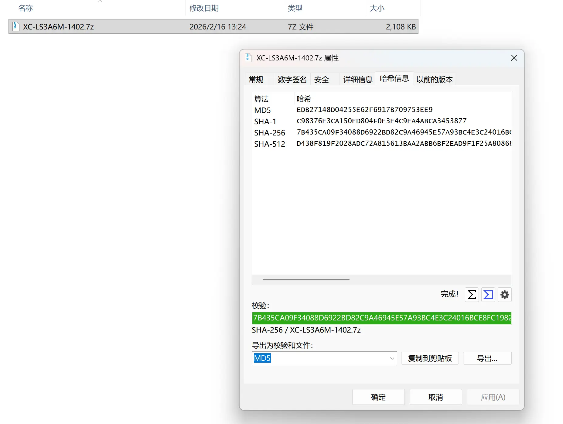
Note: If downloading from ASUS, verify the zip file because ASUS provides SHA‑256 hashes for the zip archives. This does not affect the flashing process. After verification, extract the archive because flashing software does not handle compressed files automatically.
On Windows, we recommend OpenHashTab for verification:
On macOS or Linux distributions, use the sha256sum command:
# Example with ASUS XC‑LS3A6M version 1402
sha256sum XC-LS3A6M-1402.7z
echo "7B435CA09F34088D6922BD82C9A46945E57A93BC4E3C24016BCE8FC19826E0AF XC-LS3A6M-1402.7z" | sha256sum -c
# Output: XC-LS3A6M-1402.7z: OK
Assemble and connect the programmer
Check the SPI Flash marking on your motherboard to confirm its specifications. The following table lists common motherboards and their Flash chips (subject to production batch changes):
| Motherboard | Flash model | Manufacturer | Voltage | Alternative model (for flashing) |
|---|---|---|---|---|
| XA61200 / XA61201 | GD25LQ64E | GigaDevice | 1.8V | |
| XB612B0_V1.1 / XB612B0_V1.2 | GD25LQ64E | GigaDevice | 1.8V | |
| XC‑LS3A6M | W25Q128JW | Winbond | 1.8V | W25Q128FW |
Then assemble the programmer according to the diagram. Pin positions must match exactly, starting from pin 1. Usually, the dot or notch on the SPI Flash chip indicates pin 1.
WARNING
Important: Check the Flash model beforehand. 1.8V chips cannot operate at 3.3V or 5V. Some flashing tools may detect them normally without warning, but forcing a write at the wrong voltage can destroy the Flash chip!
If you have a 1.8V chip, install the step‑down module (the green module shown in the picture).
Connect to the Flash chip
Using a SOP‑8 clip or probe
Align the clip or probe pins according to the diagram. These connectors are marked to indicate the starting position (clip pin 1 is usually red; probe pin 1 is the black side—consult your supplier for details).

Once the connection is stable, plug the other end of the cable into the programmer in the correct order. If using a probe, ensure a firm connection to avoid flashing failures due to poor contact.
Using a test socket
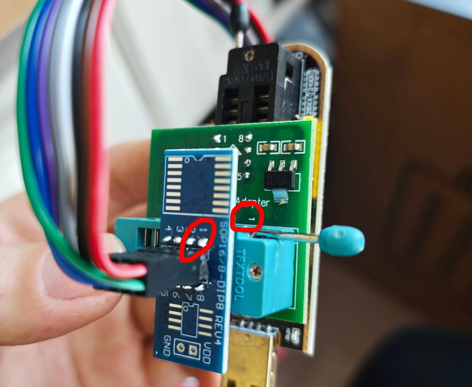
If your motherboard has a dual‑BIOS design (such as XA61200 and XB612B0) and the secondary SPI Flash chip is removable as shown below, you can use an SOP8 test socket for flashing.
After removing the Flash chip from its socket, verify the position of pin 1 (marked as ① in the picture) to avoid incorrect installation that would prevent booting.
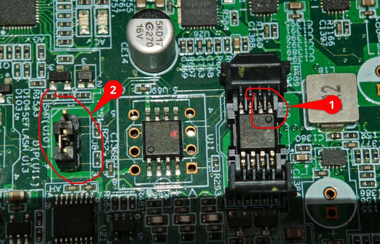
WARNING
Note: For motherboards with dual‑BIOS design, check whether the jumper shown as ② in the picture above is set correctly. This affects which firmware and settings will be used at boot.
Typically, for XA61200 and XB612B0 motherboards, the jumper works as follows: 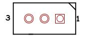
Placing the jumper on pins 1‑2 boots from the onboard SPI Flash chip; placing it on pins 2‑3 boots from the socketed SPI Flash chip.
After removal, install the chip into the test socket as shown:
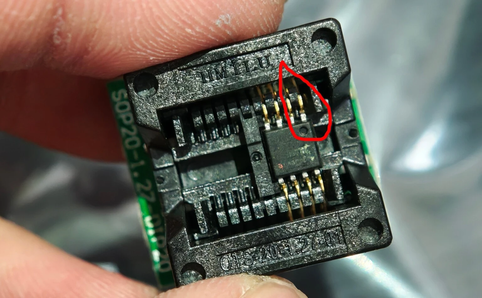
Once installed, connect the test socket to the programmer in the correct order.
(ASUS motherboards only) Using the dedicated flashing cable
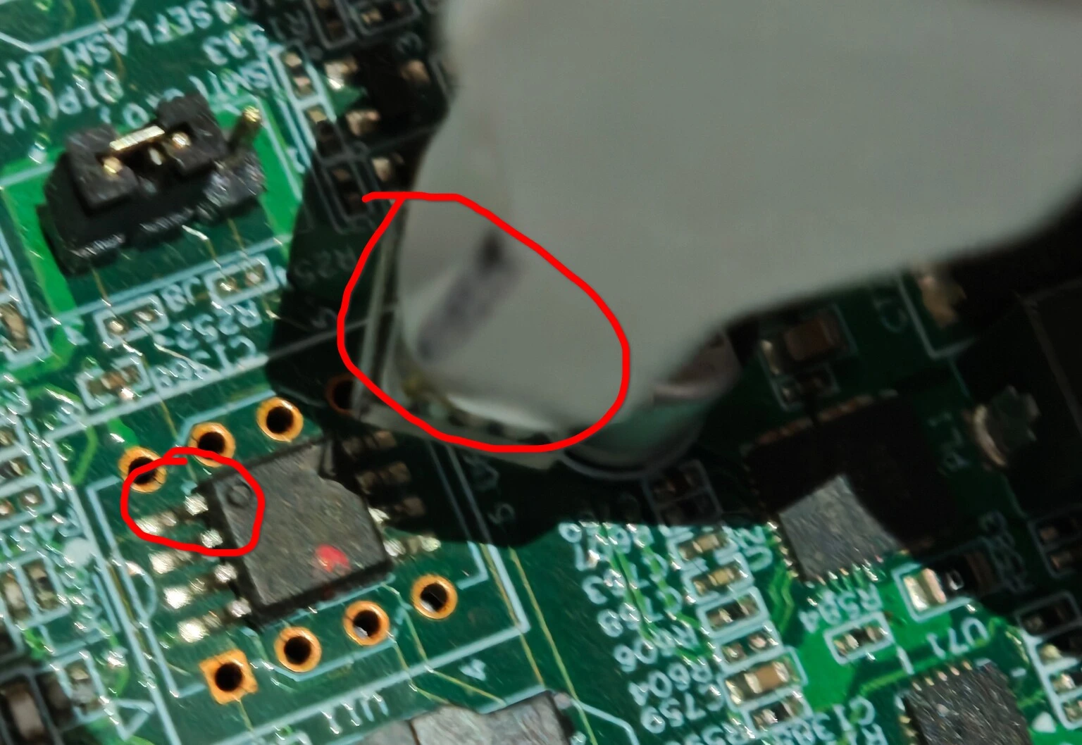
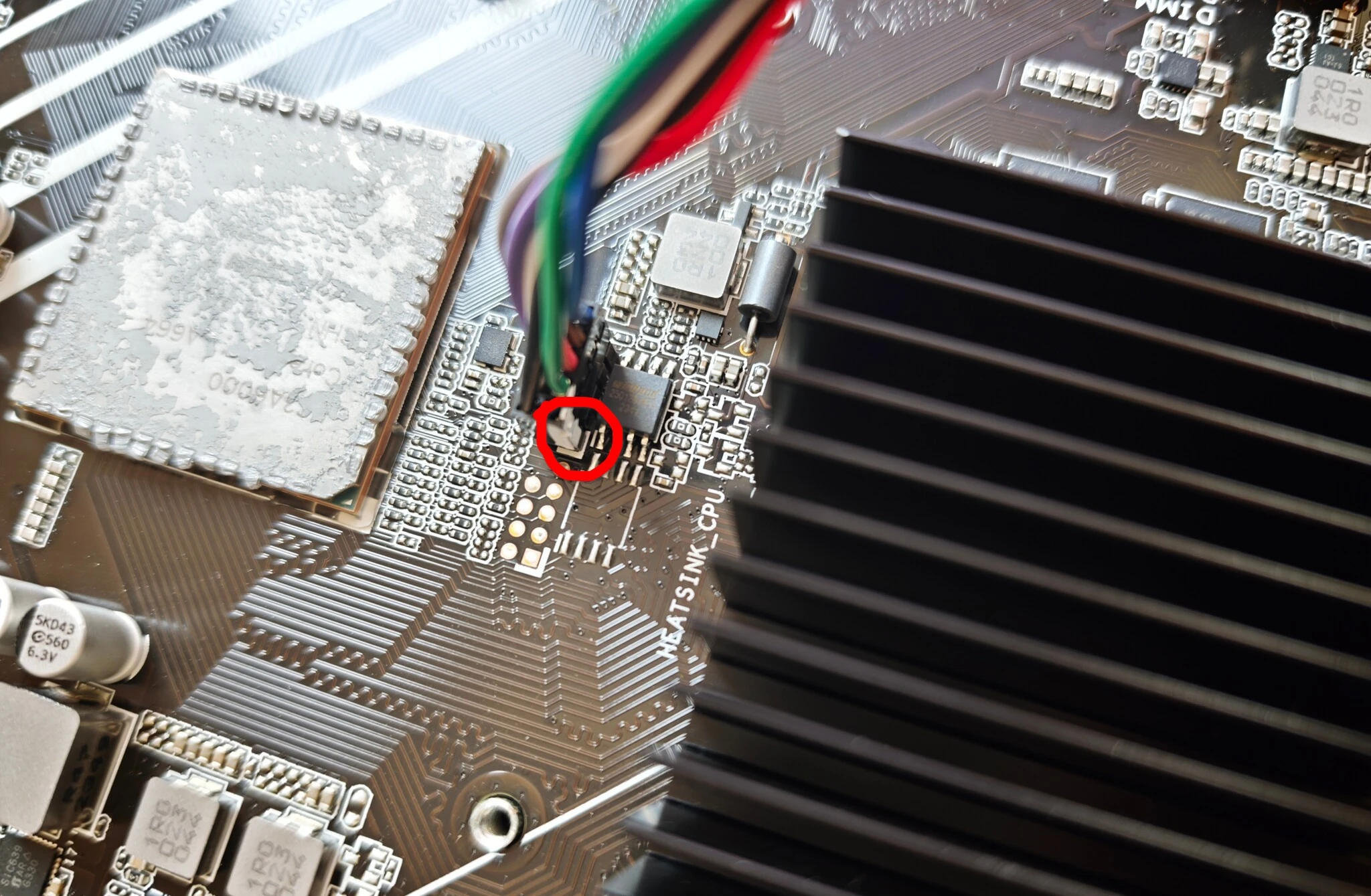
On ASUS motherboards, the SPI Flash chip that stores the BIOS firmware is located near the CPU, under the cooler. You must remove the cooler; the chip position is shown below:
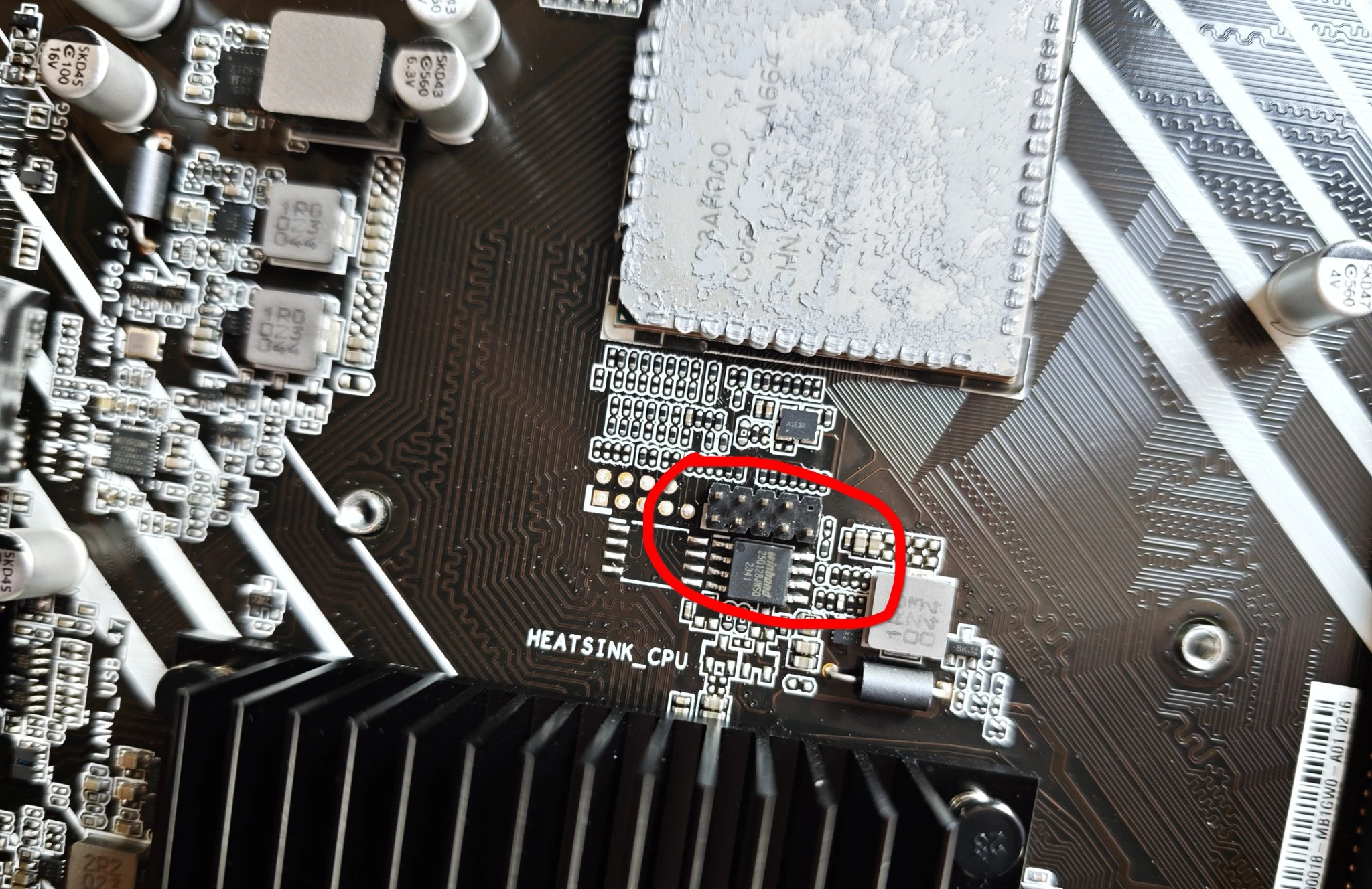
Insert the dedicated flashing cable into the connector above the SPI Flash. Make sure the white‑marked side of the connector aligns with the white mark at the bottom‑left corner of the motherboard (this indicates the starting position):
Connect the other end of the cable to the programmer as usual.
Flash the firmware
After assembling the programmer and connecting it to the Flash chip, plug the programmer into your computer and choose the flashing software according to your operating system.
Using NeoProgrammer (Windows)
Before using NeoProgrammer, install the driver provided with the software (located in 软件目录\Drivers\CH341A). Run DRVSETUP64.exe and click 安装.
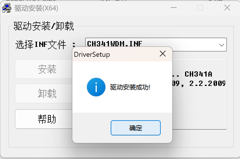
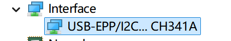
Then verify in Device Manager that the following device appears, indicating successful installation:
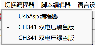
Next, identify your CH341A programmer model and select it from the 切换编程器 menu. Most commonly sold units are CH341 双电压黑色版:
Follow the numbered steps in the diagram:
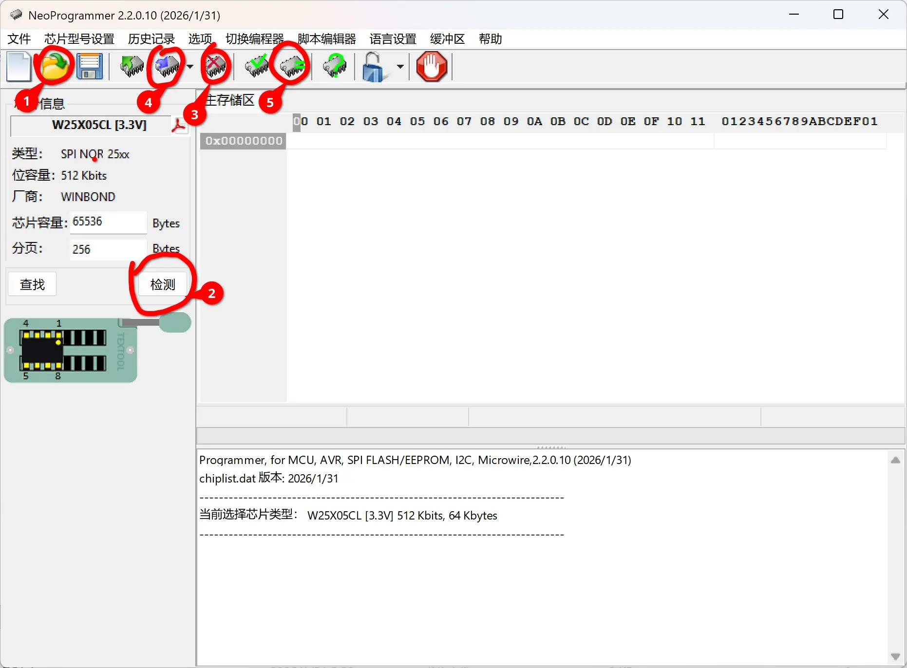
Click
打开文件and select the firmware file for your motherboard (note: rename the extension to.bin)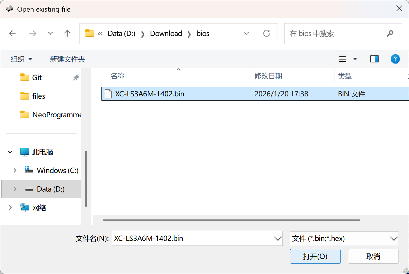
Click
检测to detect the connected Flash chip model. If the exact model is not in the database, you can use a similar one (e.g.,W25Q128JWcan be replaced withW25Q128FW). These are usually just different revisions with identical parameters.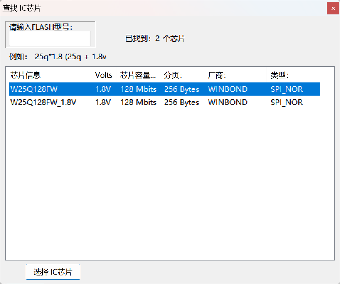
Click
擦除to completely erase the corrupted firmware. After erasing, you can optionally click查空to verify the Flash chip is empty.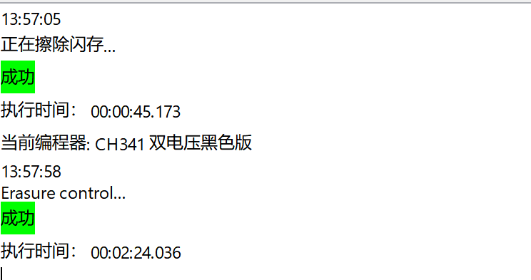
Click
写入to write the opened firmware file to the Flash chip. By default, the software performs writing and verification sequentially. Keep the connection stable throughout; otherwise unexpected results may occur.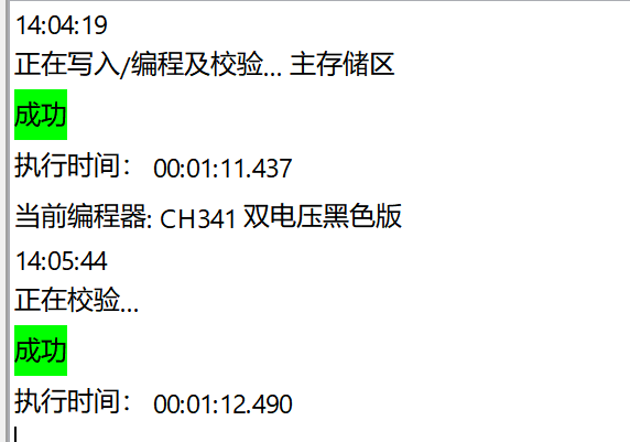
(Optional) Click
校验to confirm the written content matches the firmware file.
Using IMSProg (macOS, Linux)
Linux kernels already have mainline CH341 drivers, so no extra driver is usually needed.
For macOS, download the driver from the official site.
IMSProg is not packaged in most distributions. If available, try installing it from your distribution's repository first:
# Debian (13/14/sid)
sudo apt install imsprog

# Ubuntu
sudo add-apt-repository ppa:bigmdm/imsprog
sudo apt update
sudo apt install imsprog

# Fedora
sudo dnf install imsprog

# ArchLinux AUR
yay -S imsprog
If your distribution does not provide it, compile from source:
# AOSC OS
sudo oma install cmake gcc libusb qt-5 pkgconf wget zenity

# macOS (Homebrew)
brew install qt@5 libusb cmake pkgconf wget zenity

# Compiling all
git clone https://github.com/bigbigmdm/IMSProg.git && cd IMSProg
chmod +x build_all.sh
sudo ./build_all.sh # omit sudo on macOS
After installation, you can launch IMSProg from your application menu.
Once started, follow the numbered steps in the diagram:
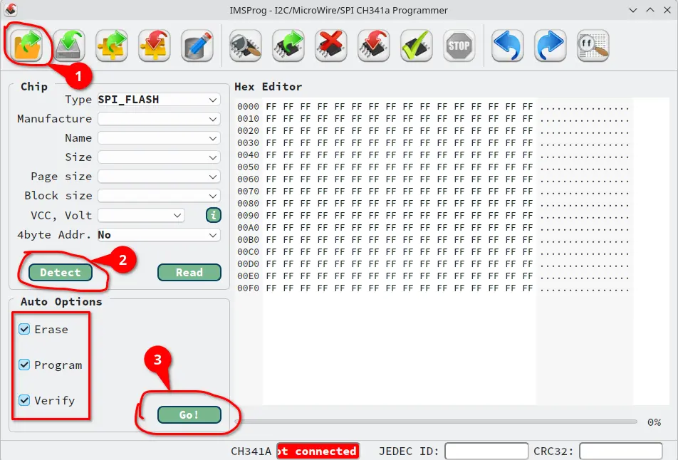
Click
Openand select the firmware file for your motherboard (note: as with NeoProgrammer, rename the extension to.bin)Click
Detectto detect the connected Flash chip model. If the exact model is not in the database, use a similar one as described above.Check all three boxes on the left, then click
Go!to begin flashing the firmware to the Flash chip. Keep the connection stable throughout; otherwise unexpected results may occur.
Verify the recovery
Disconnect all tools or cables from the Flash chip. If you removed the cooler, clean the residual thermal paste from the CPU, apply fresh paste, and reinstall the cooler.
Connect the power cable as usual, install RAM modules and storage, attach keyboard, mouse, and monitor, then power on. If the LOONGSON 龙芯 logo appears, the recovery was successful.